Wednesday, August 23, 2006

Microcontroller to RS-485 circuit

This is a circuit for connect microcontroller with Rs-485 bus


Line Length vs. Data Rate
The RS-485/RS-422 standard covers line lengths up to
4000 feet. For line lengths greater than 4000 feet, see
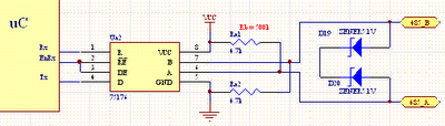
Typical Applications

RS-485 bus can carry up to 256 transceiver modules

Monday, August 21, 2006

Byte transmission diagram

When transmitting a byte, the RS232 first sends a START BIT (0),
followed by the data (general 8 bits, but could be 5, 6, 7, or 8 bits),
followed by parity bit (If no parity then there is no parity bit ) followed
by STOP BITs(one or two bit)(1). The sequence is repeated for each
byte sent. Show in picture below


Data stream = bits are transmitted from least significant bit (LSB)
to most significant bit (MSB),
Example
“A” = binary is 01000001
Data stream = 10000010

The parity characteristic can be even, odd, mark, space, or none.
EVEN
last data bit = 1 if the data transmitted had an even amount of 0 bits.
ODD
last data bit = 1 if the data transmitted had an odd amount of 0 bits.
MARK
last data bit = 1
SPACE
last data bit = 0
NONE
no parity bit transmitted

Example the bit stream transmitted
RS232 setting = characteristics 8 bits, no parity, 1 stop
Data = ‘A’
bit stream transmitted = start bit – data – one stop bit
bit stream transmitted = 0 1 0 0 0 0 0 1 0 1

Friday, August 18, 2006

Rs-232 Electrical Signal Characteristics

Picture below shows how the idealized signal looks on an oscilloscope.
MARK is a negative voltage, and SPACE is positive.

Voltage levels defined in the standard
Data signals
Space = 3 to 15 , Mark = -3 to -15 Volts
Control signals
"Off" = -3 to -25 , "On" = 3 to 25 Volts

The following is the truth table for RS-232: Signal>3V=0 Signal>-3V=1
The output signal level usually swings between +12 V and -12 V.

The dead area between +3 V and -3 V is designed to absorb line noise.

Thursday, August 17, 2006

RS232 Pinout designation DB-9

Pinout designation of rs232 in DB-9 connectors
Pin - Name - description - direction
1 -- DCD -- Data Carrier (DTE <- DCE)

2 -- RxD -- Received Data (DTE <- DCE)
3 -- TxD -- Transmitted Data (DTE -> DCE)
4 -- DTR -- Data Terminal Ready (DTE -> DCE)
5 -- GND -- Signal Ground
6 -- DSR -- Data Set Ready (DTE <- DCE)

7 -- RTS -- Request To Send (DTE -> DCE)
8 -- CTS -- Clear To Send (DTE <- DCE)

9 -- RI -- Ring Indicator (DTE <- DCE)

Rs232 DB9 pinout

RS-232

The RS-232 is a standard developed by the Electronic Industries
Association (EIA) and other interested parties, specifying the serial
interface between Data Terminal Equipment (DTE) and Data
Communications Equipment (DCE). The RS-232 standard includes
electrical signal characteristics (voltage levels), interface mechanical
characteristics (connectors), functional description of interchange circuits
(the function of each electrical signal), and some recipes for common

kinds of terminal-to-modem connections. The most frequently
encountered revision of this standard is called RS-232C. Parts of this
standard have been adopted (with various degrees of fidelity) for use in
serial communications between computers and printers, modems, and
other equipment.
Serial communication uses a transmitter to send data, one bit at a
time,over a single communication line to a receiver.
You can use this method when data transfer rates are low or you must
transfer data over long distances.


http://cnx.org/content/m12293/latest/