Wednesday, September 20, 2006
Wednesday, August 23, 2006
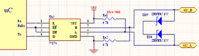
Microcontroller to RS-485 circuit
This is a circuit for connect microcontroller with Rs-485 bus
 Line Length vs. Data Rate
The RS-485/RS-422 standard covers line lengths up to
4000 feet. For line lengths greater than 4000 feet, see
Typical Applications
RS-485 bus can carry up to 256 transceiver modules

Monday, August 21, 2006
Byte transmission diagram
When transmitting a byte, the RS232 first sends a START BIT (0),
followed by the data (general 8 bits, but could be 5, 6, 7, or 8 bits),
followed by parity bit (If no parity then there is no parity bit ) followed
by STOP BITs(one or two bit)(1). The sequence is repeated for each
byte sent. Show in picture below
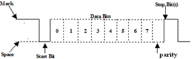
Data stream = bits are transmitted from least significant bit (LSB)
to most significant bit (MSB),
Example
“A” = binary is 01000001
Data stream = 10000010
The parity characteristic can be even, odd, mark, space, or none.
EVEN
last data bit = 1 if the data transmitted had an even amount of 0 bits.
ODD
last data bit = 1 if the data transmitted had an odd amount of 0 bits.
MARK
last data bit = 1
SPACE
last data bit = 0
NONE
no parity bit transmitted
Example the bit stream transmitted
RS232 setting = characteristics 8 bits, no parity, 1 stop
Data = ‘A’
bit stream transmitted = start bit – data – one stop bit
bit stream transmitted = 0 1 0 0 0 0 0 1 0 1
followed by the data (general 8 bits, but could be 5, 6, 7, or 8 bits),
followed by parity bit (If no parity then there is no parity bit ) followed
by STOP BITs(one or two bit)(1). The sequence is repeated for each
byte sent. Show in picture below
Data stream = bits are transmitted from least significant bit (LSB)
to most significant bit (MSB),
Example
“A” = binary is 01000001
Data stream = 10000010
The parity characteristic can be even, odd, mark, space, or none.
EVEN
last data bit = 1 if the data transmitted had an even amount of 0 bits.
ODD
last data bit = 1 if the data transmitted had an odd amount of 0 bits.
MARK
last data bit = 1
SPACE
last data bit = 0
NONE
no parity bit transmitted
Example the bit stream transmitted
RS232 setting = characteristics 8 bits, no parity, 1 stop
Data = ‘A’
bit stream transmitted = start bit – data – one stop bit
bit stream transmitted = 0 1 0 0 0 0 0 1 0 1
Friday, August 18, 2006
Rs-232 Electrical Signal Characteristics
Picture below shows how the idealized signal looks on an oscilloscope.
MARK is a negative voltage, and SPACE is positive.
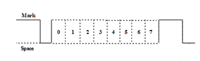
Voltage levels defined in the standard
Data signals
Space = 3 to 15 , Mark = -3 to -15 Volts
Control signals
"Off" = -3 to -25 , "On" = 3 to 25 Volts
The following is the truth table for RS-232: Signal>3V=0 Signal>-3V=1
The output signal level usually swings between +12 V and -12 V.
The dead area between +3 V and -3 V is designed to absorb line noise.
MARK is a negative voltage, and SPACE is positive.
Voltage levels defined in the standard
Data signals
Space = 3 to 15 , Mark = -3 to -15 Volts
Control signals
"Off" = -3 to -25 , "On" = 3 to 25 Volts
The following is the truth table for RS-232: Signal>3V=0 Signal>-3V=1
The output signal level usually swings between +12 V and -12 V.
The dead area between +3 V and -3 V is designed to absorb line noise.
Subscribe to:
Posts (Atom)

 Posts
Posts


